

I recently acquired an intertest in Slow Scan TV (SSTV) and one of the most popular frequencies for SSTV exchanges is 14.230 MHz. My 270 foot Off-Center Fed Multiband has a Standing Wave Ratio (SWR) of 3:1 on 14.230 MHz before tuning so I was looking for better efficiency. Here is a great presentation on the end-fed by K1RF if you are interested in learning a lot more.
Here’s my list of parts:
- Plastic Project Box
- Magnet Wire (Enameled #14 AWG or similar)
- Torroid Cores (I used three Mix 43 Mouser #:623-5943003801)
- 100 pF Capacitor (Mouser #:75-HVCC203Y6P101MEAX)
- Wire for Antenna (I used #14 AWG)
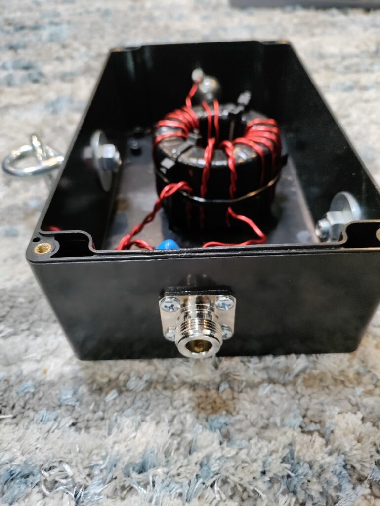
- N or SO-239 Connector
- Miscellaneous nuts and bolts
- Cord/Rope to hang the box and antenna end
- Zip ties
- Electrical tape
- Solder and solder gun
- Drill and drill bits
- Cable (I used 100 feet of LMR 400)
- Ground connection (I used the MFJ-270 capable of 400 watts). Remember the coax shield is a counterpoise.
Here is a little more explanation of what I was trying to do… I wanted a very specific single band antenna tuned to 14.230 in the 20m band, preferably end-fed for the location I wanted. Most EFHW antennas I found online for purchase were rated at 100 watts (some up to 300w) peak envelope power and are okay for my 100w radio if I were in single side band mode which has a lower duty-cycle. Digital is different. The duty cycle is much more intense lending itself to a max PEP of maybe 30w on the 100w pre-made antennas found on DX Engineering (I reached out to the manufacturer Par EndFedz to confirm their design max before attempting the build). My hope is that my three core design should do the trick for whatever power I want to run in the future on 20m. By the way, these are what I had left over from a previous similar project so I found a good use for them here.
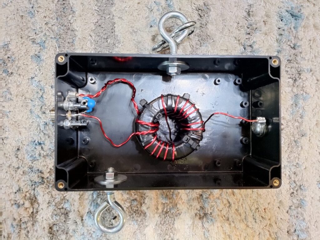
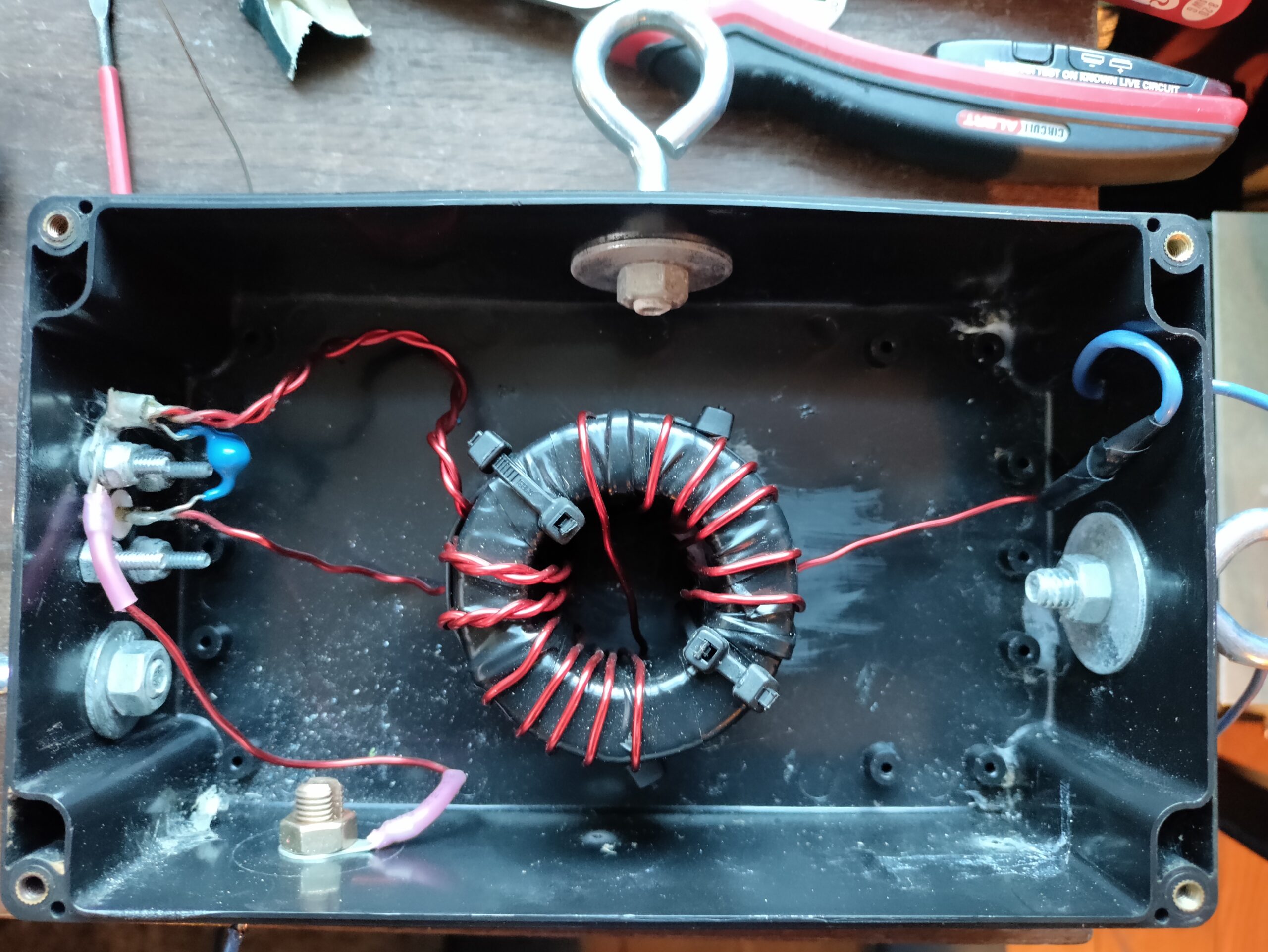
A transformer is needed for this type of antenna to match the high-impedance feed point down to something that is suited for the cable and radio (aka 50 ohms). With an EFHW, a 49:1 is needed for this. I used the 49:1 transformer design found on Ham Radio Archives – Jason Jardina which is an excellent resource and explanation of the transformer.

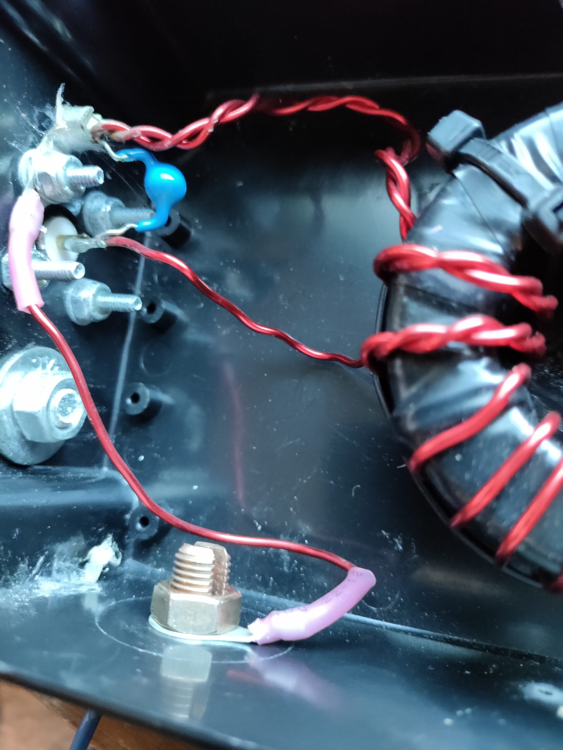
There really wasn’t much to the winding of the cores, but of note, I did use electrical tape because the enameled wire I used got nicked really easily (even though the cores are not conductive and trapped heat may be an issue). Cores are zip-tied together as well as to the box itself via a couple holes I drilled in the back (later sealed). Also, I fiddled with the windings a bit to make sure I got the results I wanted. I tried to use a plastic bolt to hold in the cores but that did not work so the zip ties were my second choice. I am unsure of the heat generated so I may need to check this from time to time. I am hoping with the large box and three cores, heat will be less of an issue.
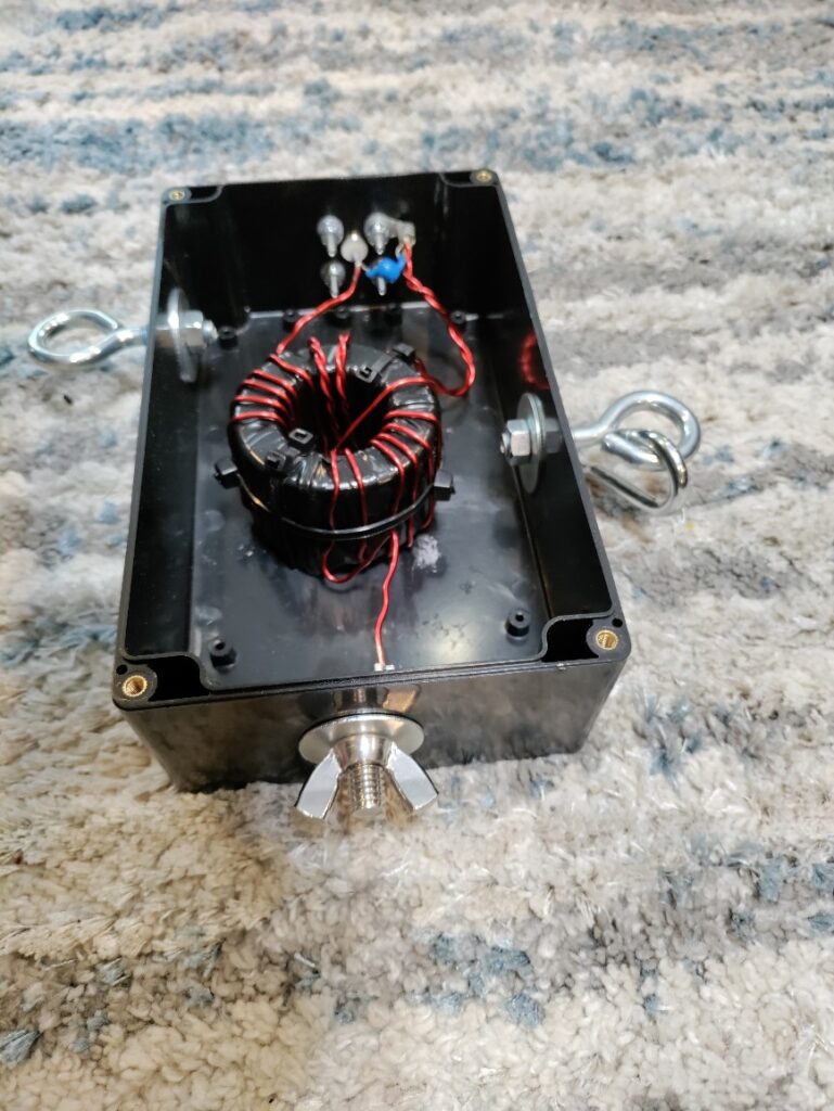
The hook in the center is for hanging, the other hook is for stress relief of the connector. This early version had a wingnut for the antenna connection, but I ended up changing that out for a third eye-bolt.
Okay so here’s where I goofed with what I wanted. I thought I had 14 AWG stranded wire for the antenna. Turns out I had solid. But I was really excited to get this on the air, so I used it anyway. Definitely not going to tolerate flexing as much in the trees but it still radiates and when it comes time to replace it, I’d have to buy new wire anyway. So just kept it moving…
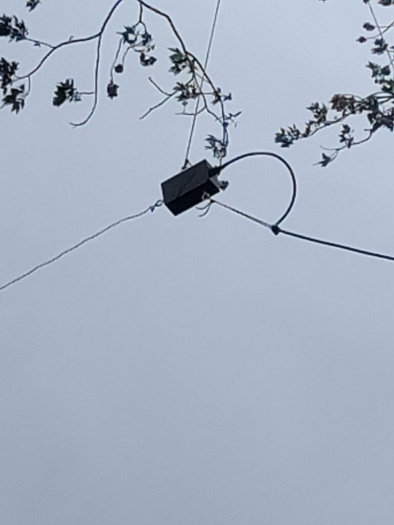
The image is at an odd angle, so I assure you, that LMR400 is not a sharp kink! I have a piece of automotive fuel hose over the LMR400 with a pipe clamp holding the paracord in place. Paracord is also what I am using to hang the box with. There are small weep holes in the bottom as well.

Since trees move, there is always strain on the antenna wire. Sometimes I loosen antenna ropes if there is predicted high winds. I also have one antenna (80m EFHW) with springs inserted in the rope section. I was looking for a good insulator at the local hardware store when I found a cheap automotive rubber strap. Insulator and flexible, perfect! I probably would have preferred something with even more give considering I have solid wire, but again, that’s fine for now. The nice thing about wire antennas is that a broken wire is an easy fix.
The paracord hanging is my pull strap to lower to ground level to trim antenna to resonance. I started with a significantly longer antenna than I needed (tuned at about 9 MHz at start) and then gently cut the wire in small increments to get it to almost exactly 14.230 MHz. The pull down string made this fast and easy. I raised it to full height every few cuts to see exactly what the readings would be raised.
Using my AA-650 antenna analyzer, I obtained the following readings which was better than I had hoped:
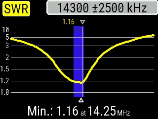
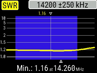

14.230 MHz has impedance of 47.8! RL is very low at 22 dB as well.
With those results, I have also been using this antenna for FT4 and FT8. I can hear the difference in those modes when I switch the antennas. I definitely hear more audible frequencies in the mix.
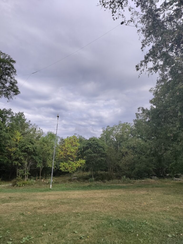
And here is the final setup!

Interestingly enough, the day after I finished this project, the ARRL sent out an advertisement with a kit for a multiband EFHW with a rated power of 250 watts (ARRL EFHW Kit). Might be a good place to start experimenting for some folks!
Updates from November 2024:
The branch broke that was holding this up so I took the opportunity not only to replace the radiator wire with stranded 14g THHN, but I also made some slight modifications. Notice after about four (4) years of use, my concern of overheating the cores in the Virginia sun with electrical tape left no noticeable concerns.
Updated design includes a dedicated counter-poise wire (bottom)
Close-up of the copper split bolt I used.